Showing posts with label PTFE. Show all posts

Monday 3 May 2010

Plumbstruder

Brian Reifsnyder asked for volunteers to test his hybrid PEEK and PTFE insulator design, so I used it for the hot part of my Mendel extruder to start with. The drive mechanism is Wade's design.


It worked well at first, requiring little force to extrude PLA, but got harder and harder until eventually it completely jammed. This video below shows that even with the nozzle removed and starting with a completely empty barrel I couldn't push more than about 15mm of filament through it.


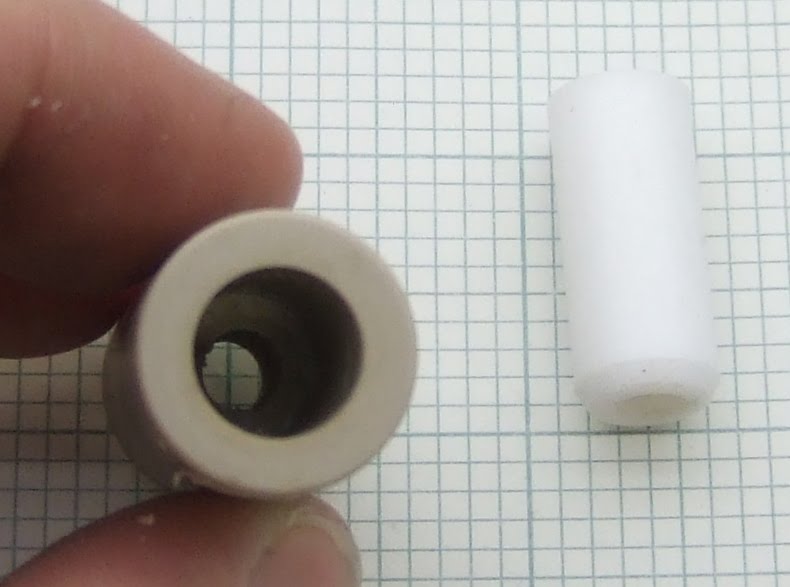
The reason was that the PTFE liner had slipped a little leaving a small gap between it and the end of the brass heater barrel.


This makes the extruder jam completely solid. The reason is that PLA goes rubbery above 50°C, so any pressure on it makes it expand width wise and grip the side of the tube. If there is a gap that it can expand into it locks the filament.

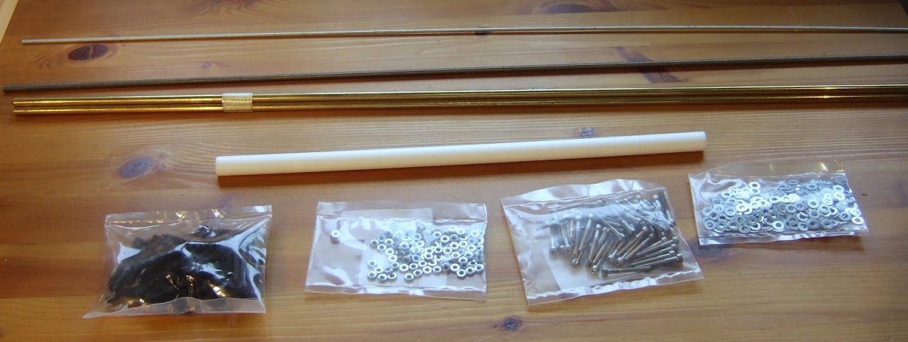
I stripped it down, cleaned it out and reassembled it with some washers to hold the PTFE down.


Brian has added a circlip to the design to solve the problem.


I haven't tested this version yet because I ran into another problem before it arrived. When I started using a heated bed for PLA the extruder jammed again. This time it was because the top end of the insulator got hotter than the glass transition of the PLA, so it swelled as it went into the insulator and jammed in the tapered entrance. There was also some leakage around the threads.


The reason it got too hot is a combination of the heated bed, the fact that I used an uninsulated heater with a large surface area, and the fact that the Mendel carriage traps the rising heat.


I decided to try out an idea I had a while ago, which is similar in intent to Brian's scheme. Instead of putting PTFE inside PEEK to stop it expanding I put it inside a 15mm copper pipe. This not only totally constrains it so it cannot swell, it also removes heat from it, shortening the transition zone. I am calling this one Plumbstruder. Here is a sketch of the layout: -


The end of the copper pipe is closed off by soldering an end cap on and then drilling it out to leave a lip to support a PEEK disk which the barrel screws into as well as into the PTFE. That means the PEEK supports the extrusion force, as in Brian's design, but I also use the thread in the PTFE as a seal rather than just having a compression joint.

The copper pipe gets hot so I coupled it to a big heatsink with a copper flange.


I turned this from a solid block of copper a friend gave me (thanks Paul). I soldered it onto the pipe and screwed it onto the heatsink.


I turned the one piece nozzle / barrel from hex stock so it has a nut shaped flange in the middle to make it easy to screw in and also gives the aluminium heater block something to tighten against.


I had to turn down the PTFE to be a tight fit inside the pipe. I was hoping to find a size where the ID of the pipe matched the OD of the PTFE. 22mm copper pipe has an ID of 20mm, so theoretically 20mm PTFE rod would fit. In practice I have found that PTFE rod is about +/- 0.5mm so, unless you were lucky, the fit would not be good enough.

Even with a big heatsink it was getting uncomfortably warm so I added a tiny fan.


I have been using this extruder on my Mendel for a few weeks and it is totally reliable, with no sign of leaking. I think that of all the extruders I have made, this one needs the least force to extrude. I can push plastic through by hand at high speed with ease. For an extruder to work I think the transition zone needs at least two of the following three attributes: short, slippery or tapered. Unfortunately a short transition zone seems to mean using a heatsink, which is not ideal for a moving head machine.

I also think a short melt zone improves the accuracy by reducing the start-stop time. In that respect this design is not ideal, although it is no worse than the standard design.

Wednesday 4 November 2009

No compromise extruder

I have settled on using vitreous enamel resistors embedded in an aluminium block for the heater. I think they are the easiest heater to make and likely to be the most durable. They also work fine with simple bang-bang control, whereas it would appear that the Nichrome and Kapton version requires PID.

One of the aims of my new design is to reduce the amount of molten plastic to minimise ooze. Also less molten plastic means less viscous drag. I also wanted to reduce the thermal mass (to reduce the warm up time) and completely cover the hot part with insulation to allow a fan to blow on the work-piece without cooling the nozzle.

To achieve these aims I switched to a smaller resistor (same resistance but less wattage) and mounted it horizontally rather than vertically. There is some risk that the resistor may fail but I think as long as it has good thermal contact with the aluminium block, so that its outside temperature is less than 240C, then I have a good chance it will last.

The smaller resistor also means a much smaller surface area so less heat is lost. T0 keep the molten filament path as short as possible I combined the heater and the nozzle and made it from one piece of aluminium. That also gives very good thermal coupling between the nozzle tip, the melt chamber, the heater and the thermistor.


I turned it out of a block of aluminium using my manual lathe and a four jaw chuck, but I think I could also mill it out of 12mm bar using HydraRaptor.

A feature that I have used on my previous extruders is to cover as much of the nozzle as possible with PTFE. That stops the filament sticking so that it can be wiped off reliably with a brush. It also insulates the nozzle.

My previous nozzle cap implementations have been turned from PTFE rod. The downside of that is that the working face, that has been cut and faced on the lathe, is not as smooth and slippery as the original stock.


To cover the face of this version I used a 3mm sheet of PTFE so it has the original shiny surface.


Normally PTFE is too slippery to glue so my original plan was to screw it on with some tiny countersunk screws. However, the sheet I bought was etched on the back to allow it to be glued, so I stuck it on with RTV silicone adhesive sold for gluing hinges onto glass oven doors.


To insulate the rest of the heater I milled a cover out of a slice of 25mm PTFE rod.


I normally stick items to be milled onto the back of a floor laminate off-cut using stencil mount spray. I didn't think that was going to work with a PTFE cylindrical slice that is only a little bigger than the finished item. Instead I milled a hole in a piece of 6mm acrylic sheet that was already stuck down with stencil mount. The hole was slightly smaller than the PTFE so I faced it and chamfered it on the lathe and then hammered it in.


I roughed the shape with a 1/8" end mill and then sharpened the internal corners and cut the slots for the resistor leads with a 1mm end mill. I tried to mill the whole thing with a 1mm bit but it snapped due to a build up of burr in the deep pocket. On reflection it was silly to expect to be able to mill deep pockets with a 1mm bit and of course it is much faster to rough it with a bigger bit.


I used my normal technique of taking 0.1mm depth cuts at 16mm. That allows me to mill plastic with no coolant, but I expect I could have made much deeper cuts in PTFE. It mills very nicely, probably because it is soft and has a high melting point and low friction.

I haven't done any milling for a long time so for anybody new to my blog here is my the milling set-up: -


It is simply a Minicraft drill with some very sturdy mounts. The spindle controller I made originally would need its micro replaced as the one I used has a bug in its I2C interface. Instead I just connected it to the spare high current output on my new extruder controller.

The remaining part of the extruder is the stainless steel insulator.


I made the transition zone shorter than the last one I made because I wanted all of the inside of the transition to be tapered. The aluminium sleeve carries away the heat from the cold end of the transition to an aluminium plate that forms the base of the extruder. That in turn carries the heat to the z-axis via an aluminium bracket. I used heatsink compound on the joints.

Here is a view of the bottom half of the extruder: -


And here is a cross section showing the internal details: -


So that was the plan, what could go wrong? Well everything really! The first problem was that the resistor shorted out to the aluminium block. The smaller resistor only has a thin layer of enamel over its wire. Normally I wrap aluminium foil round it to make it a tight fit. I didn't drill the hole big enough so it was a tight fit with only one layer and pushing it in abraded the enamel. The solution would be a bigger hole and more layers of foil, but I just glued it with Cerastil as a quick fix. Of course it only failed after I had fully assembled it and run some heat cycles so I had to strip it down again to fix it. Not easy once the wiring has been added.

The next problem is that it leaks. I think it is because I dropped the extruder when I was building it and bent the thin edge at the end of the stainless steel barrel. That forms the seal with the heater block, so even though I straightened it I think the seal is compromised. I keep tightening it and thinking it is fixed but after hours of operation plastic starts to appear at the bottom of the PTFE cover.

The other problem is that mostly it extrudes very well, I now do the outline at 16mm/s and the infill at 32mm/s, but sometimes the force needed to push the filament gets higher and causes the motor to skip steps, or the bracket to bend so far that the worm gear skips a tooth.

I have made several objects taking between one and two hours and it worked fine. Other times, mainly when I was making small test objects with Erik, it will completely jam. Actually it seems to jam when it is leaking badly, which implies the pressure of the molten plastic is much higher as well as the force to push the filament. The only explanation I can think of is there is an intermittent blockage of the nozzle exit. More investigation required.

Saturday 3 May 2008

Experimental extruder

I want to see how much of the Darwin design I can make out of HDPE as that is the plastic I have the most of and is the easiest to get hold of. It should also be the cheapest but I think I got a very bad deal with mine.

To extrude HDPE quickly, without losing accuracy, requires a fan blowing on the work piece while extruding at around 240°C. The PTFE insulator in the extruder starts to lose its strength under these conditions and it also extends about 0.5mm due to thermal expansion. The JB-Weld heater insulation also degrades rapidly. To address these problems I am working on a design using stainless steel as the insulator, which I first blogged here. Here is a second lash up I made to progress the idea :-


At the bottom is a brass nozzle made by the man himself, Adrian Bowyer, and is described here. It has already been superseded with the anti-ooze design shown here.

Above that is a brass barrel that came from BitsFromBytes, with my experimental Cerastil heater on it. I attached a thermistor to the barrel with JB-Weld.

The brass barrel is screwed into the end of a 1/4" stainless steel tube. The other end has been tapped with a 1/4" UNF thread and screwed into a small north bridge heatsink from a PC motherboard (40 x 40 x 15mm). I drilled through the centre and tapped it. To lock it in place and give a good thermal connection I made a square nut from a piece of 10mm aluminium bar. I spread heatsink compound on the threads.

The top of the stainless steel tube is screwed into an old PTFE barrel to join it to the pump. The barrel had swollen so that it wouldn't hold an M6 thread anymore, but fortuitously it seems to have swollen just enough to match 1/4" UNF.

This is by no means the final design, it is far too long and flimsy, it's just to test the concept using existing parts.

I also wanted to try insulating the barrel and nozzle with PTFE. I made an end cap that fits over the nozzle by plunging an 8mm end mill into a 12mm PTFE rod :-


The idea of this is to keep the fan wind off the nozzle and also give it a non-stick surface so that when filament curls upwards and will not stick to it. I also insulated the stainless steel tube with a piece of 12mm PTFE rod with a 7mm hole drilled through it. Here is the completed assembly :-


The gap in the PTFE where the heater and thermistor are and where the wires emerge is covered with fiber class wool. I hate the stuff, I only have to think about it for it to make me itch all over. It is a much better insulator than PTFE though, but I wanted something smooth and slender to not disrupt the airflow from the fan too much.

The wires are sleeved with PTFE insulation and then plugged into a floppy drive connector. So everything at the hot end is good for about 300°C.

How well does it work? Well it took me a long time to be able to get it to extrude HDPE semi reliably. Thermally it works well. With the fan off and the barrel at 250°C the heatsink only gets to about 45°C, easily cool enough to mate with HDPE, ABS and probably PLA and PCL as well. With the fan blowing it cools down to room temperature. The heater power goes from about 60% to 80% so the insulation works well enough. A better idea might be to lag the pipe with a thin layer of fiberglass wool and then wrap it with PTFE baking parchment to give it a smooth outer surface. Or maybe an outer metal pipe with fiberglass in between.

Mechanically it is not that great. It seems to a need lot of force to extrude. I had to open up the hole in the nozzle from Adrian's 0.4mm to my standard 0.5mm. I also had to up the temperature to 250°C. I think this is mainly due to where I am measuring it and how I calibrated the thermistor. Previously I measured the nozzle temperature and calibrated it with a thermocouple inserted into a hole in the nozzle. With this version the thermistor is in a notch on the surface of the heater barrel and I calibrated it with a thermocouple inside the empty barrel. Looking at the value of beta that I got I think that it is considerably hotter inside the barrel than the thermistor is outside. I am not sure how this is. With the heater on the outside of the barrel I can't see how the inside could be hotter. Perhaps the thermal connection of the thermistor to the barrel, via JB-Weld is not as good as it it could be. When sited in the acorn nut nozzle it was half buried in a hole.

Even with the nozzle removed it is quite hard to extrude 3mm filament by hand. Part of this has to do with how long the total barrel is and the fact that it has three joints. The inside of the stainless steel barrel is not as slippery as the PTFE. It might also be the case that the molten section extends further up the barrel causing more viscous friction. I plan to shorten the whole thing considerably: I will combine the clamp with the right angle bracket and take the tube right up to the base of the pump. I will support the heatsink with a cradle structure resembling an upside down table. More importantly, I will shorten the heater barrel by combining it with the nozzle and screwing the tube into it. Making it from aluminium, which is two and a half times a better conductor than brass and easier to machine, should make it easier to get a consistent temperature measurement.

As there is a continuous temperature gradient down the stainless steel, the point at which the plastic melts will be about halfway up so I think the heated nozzle can be quite short indeed. The limiting factor is how long it takes the heat to get to the centre of the filament with the very poor thermal conductivity and high specific heat capacity of the plastic.

Here is an HDPE version of the opto bracket with my best PCL version behind :-


I have no idea why it is so grey. It is not as neat as the PCL one but most of the errors are due to blobs forming when the extruder moves between extruding. These cause the nozzle to be displaced sideways when it gets close because it is so flimsy. Shortening it and supporting it properly will improve matters for sure. I also need to incorporate Adrian's anti-ooze valve somehow.

Sunday 22 April 2007

Too thick

I decided to order the parts to make the extruder so that they could arrive while I was writing the firmware. The official RepRap design I am working to is here. Forrest Higgs has a simpler design here but as I have a lathe and I don't have a blowtorch I decided to stick with Adrian Bower's original for my first attempt.

I got a lot of the mechanical parts from Farnell and was most impressed with their free next day delivery.


Some of the part numbers had gone obsolete, mainly due to ROHS, so I made the following substitutions :-

Description

Original

Substitute

Steel M5 Studding517343517409
Steel M3 Nuts7587968861250
Steel M3 Washers1496878861447
Steel 25mm M3 cap screws 1001658838887

10mm PTFE rod was out of stock but I found a cheap source of 12mm rod on eBay at Fantastic Plastic.

I also ordered a 5Kg reel of HDPE filament to get started with. It cost £85 including shipping. I plan to recycle milk bottles eventually but that will require a grinder. A four pint milk bottle weighs about 25g which makes them worth about 42p each. They must cost a lot less than that to make so the implication is that this stuff, sold as plastic welding rod, is overpriced.


The reel is a bit big and heavy to mount on the machine so I will probably have to re-spool it somehow.

It is a good job that I bought the filament before I made the extruder. The instructions specify to drill out the barrel to 3mm but my filament measures 3.2mm! I have ordered a 3.3mm drill from www.toolfastdirect.co.uk.

I also bought some nichrome wire to make the heater and some J-B Weld to attach it to the barrel and provide the electrical insulation and thermal coupling.


This stuff is rated up to 600°F. It is a departure from the original design which uses PTFE tape so it will be a bit experimental. I am hoping the thermal coupling will be good enough to allow me to use the resistance of the nichrome wire to measure the temperature rather than having a separate thermistor.